The all-in-one Brushless DC Motor driver
About a year ago I went through my stash of salvaged electronic parts and came across boxes of motors from hard-drives I took apart. Now these aren’t normal motors with two leads that you just apply current to. These are motors with three or four leads that must be driven in a specific pattern. They are called brushless DC motors (Wikipedia page).
Now the problem that I had was that I didn’t know how to drive them. So I started to read, watch and learn everything about brushless DC (BLDC) motors and decided to make my own sensorless BLDC driver. I decided to start simple so I designed a logic circuit in Logisim, a free digital logic simulator for simple circuits (link to dev. page). Sadly, its development is suspended but the final product is the best in comparison with similar programs for Mac.
So I dusted off my skills in logic design and made the BLDC driver using only JK flip-flops, an OR gate, a NOR gate and a multiplexer.
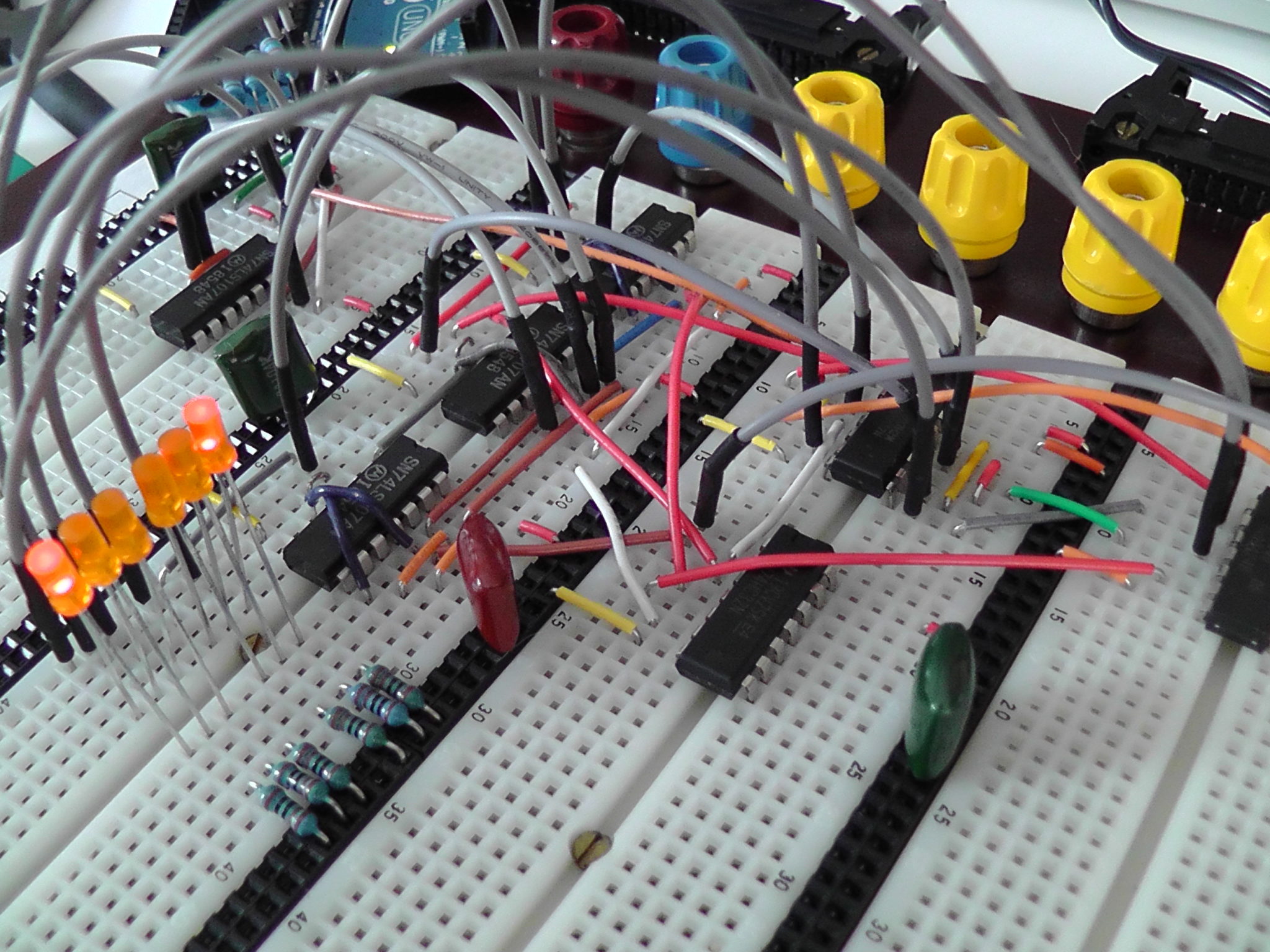
Even though the logic simulation worked, I wanted to make sure the circuit would function in real life. So I took my largest breadboard and reconstructed the design using through-hole components.

Now that I had tested the logic in real life, it was time to port this to a schematic. I decided to use SMD parts of the 74HCxx family. There is no particular reason for choosing this logic IC family, I was just familiar with it.
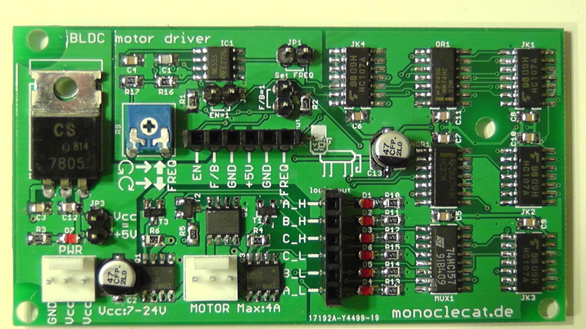
I designed a circuit that can be used as a standalone driver for BLDC motors. All you have to do is supply it with a voltage of 7-24 volts. Plus, you have the following features:
- The signal generating logic needs a clock source. You can either use the on-board clock source (an NE555 configured as an astable multivibrator) or provide an external clock. When using the on-board clock source, the BLDC motor can be driven at speeds between 48 and 17000 RPM. The clock source is selected using a jumper.
- An ENABLE input must be pulled high for the logic to function. There is also a jumper on-board for this.
- A FW/BW input controls the spin direction of the motor. A jumper on-board can also be used.
- There are two power nets in the schematic, Vcc and ‘+5V’. ‘+5V’ is the output of a 7805 regulator that takes Vcc as an input. There is a jumper that can be used to connect Vcc and ‘+5V’. This should be done when you are already supplying regulated 5 volts to the board.
- On the PCB you already have the MOSFET h-bridges needed to drive the loads of the motor. IRF7389 chips are used. They can handle currents of up to 4A. All you have to do is plug in your motor and you’re good to go.
- If you don’t want to use the on-board MOSFETs, you can tap the logic outputs through a header. This is useful when your motor draws current in excess of 4A or when you fried the IRF7389 chips for some reason (read on…).
- I took a lot of time designing the silk-screen of the board to add pin descriptions and names to make it user-friendly.


I ordered the PCBs from Smart-prototyping.com and they arrived in a flash. I carefully assembled and soldered one of them and cleaned the flux off of it to make it look nice.


And then I applied power
The PCB was finished and I wanted to test it out. I first plugged the board in to 12V, then I set the jumper for “Set FREQ” (clock source provided by the 555 timer). A few seconds after setting the “EN=1” jumper (enabling the logic), Q2 and Q1 went up in flames. I immediately removed power but the damage was irreversible.
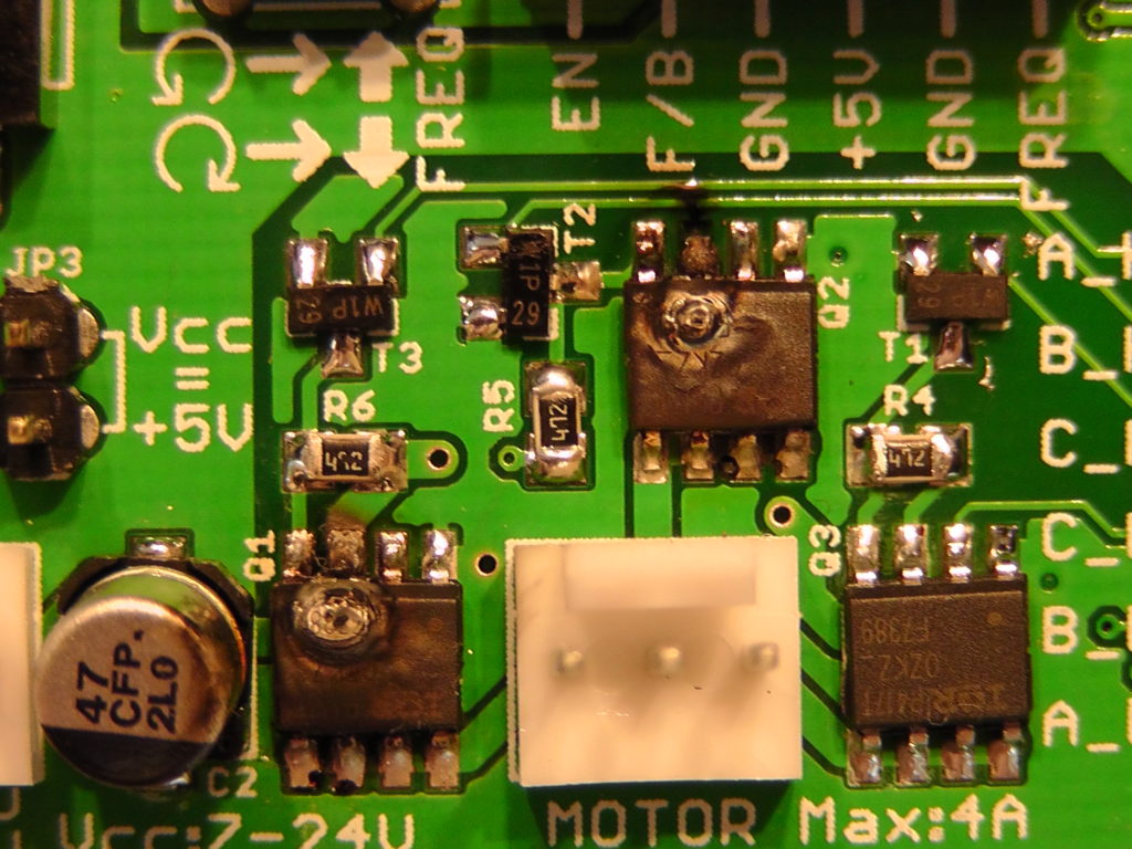
After analysing the circuit, I found the flaw:
- The JK flip-flop ‘JK1’ was faulty and didn’t function. This resulted in JK2B acting on its own, continuously triggered by NOR1A, and functioning as a frequency divider (dividing the freq. by 2). This resulted in the P- and N-Mosfet of two h-bridge groups turning on at the same time, resulting in a short circuit and destroying them.
After replacing the ‘JK1’ IC, desoldering the on-board h-bridge circuit and building an alternative h-bridge circuit on a breadboard, I applied power and … everything worked! The BLDC motor started humming away. Turning the potentiometer ‘R9’ counter-clockwise accelerated the motor.
Here’s a demonstration video. You can see the lowest clock frequency possible is 300Hz and the highest clock signal the motor can compete with is about 2.2kHz. Note that this is the clock signal frequency and not the spin-frequency of the motor.